

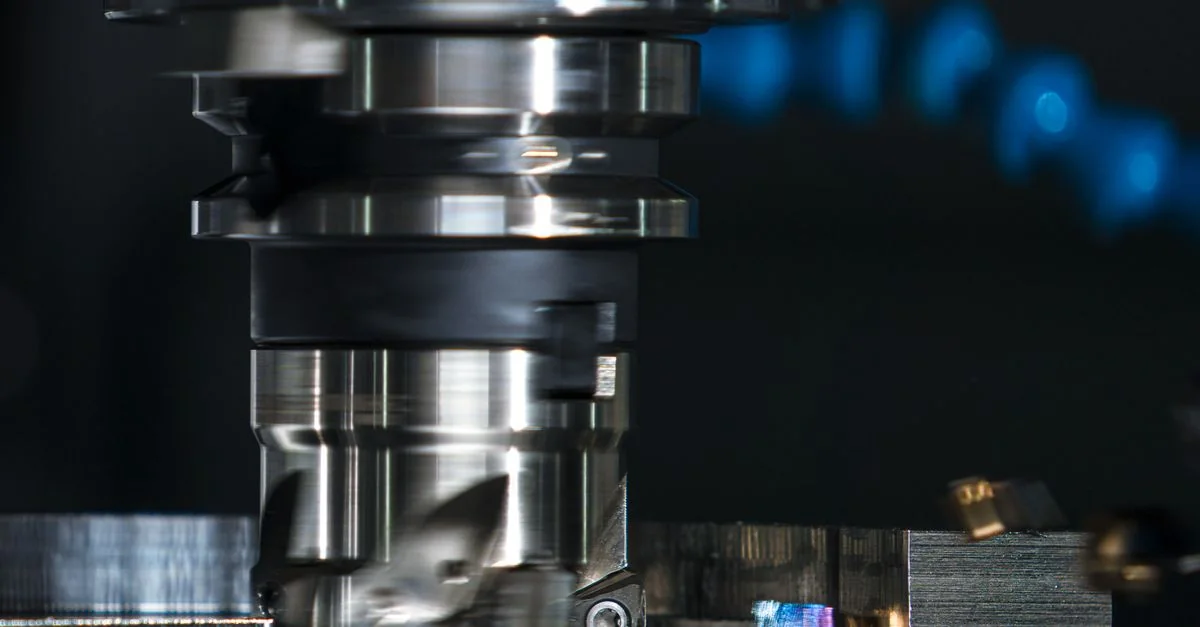
Machine tools & auxiliary drives
Machine tools combine spindle, coolant and chip-handling duties with very different torque and stopping requirements. Select each motor circuit independently.
Load characteristics & existing operating problems
A machine tool is not a single load: the spindle needs suitable cutting speed and torque, coolant pumps need flow, and chip conveyors can jam. Operation above spindle base frequency introduces motor and mechanical limits, while heavy low-speed cutting raises cooling concerns. Diagnose original equipment faults, belt drives and bearings before selecting a larger drive as a substitute for mechanical repair.
- CNC / machine PLC
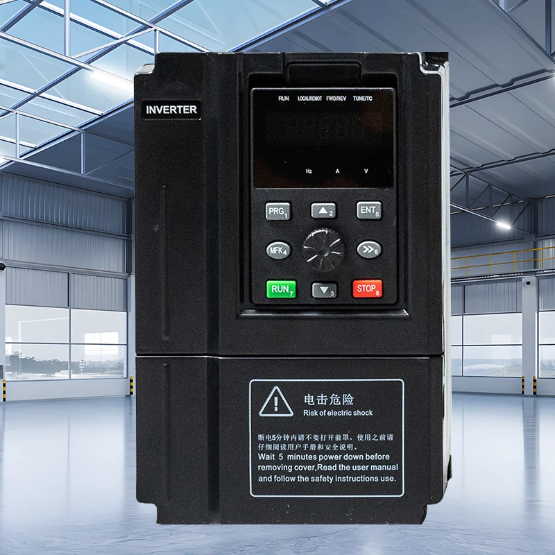 Hailing 750verified drive interface
- compatible motor
Independent machine safety chain
System composition & control sequence
The original CNC or machine PLC supplies permissions and speed references, with independent matching and protection for each motor. Spindle, coolant and chip removal may require sequencing, such as coolant confirmation before machining. This is machine-controller logic, not an assumed general-drive feature. Preserve emergency stops, guard locks and safe restart, and verify terminal meanings, signal polarity and fault feedback when replacing a drive.
Selection inputs & control requirements
Record the motor nameplate, base frequency, required speed range, low-speed duty, braking energy and CNC signals. For spindles confirm rated speed and permitted frequency; a listing’s frequency limit is not a spindle speed guarantee.
| Data to collect | Why it matters | Reference |
|---|---|---|
| Motor base frequency and current | Distinguish general motors from dedicated spindles and assess continuous and low-speed duty. | Motor nameplate and original machine records; 750/3000 overviews are not spindle manuals. |
| Mechanical speed limit and ratio | Prevent a frequency setting from overspeeding the spindle, tool or bearings. | Machine/spindle manufacturer confirmation; drive frequency range is not mechanical permission. |
| Braking inertia and stop requirement | Assess deceleration energy and allowable stopping time, including any special braking requirement. | Exact-model braking configuration and equipment risk assessment required. |
| Reference and interlock interface | Verify analog references, discrete permissions, fault states and recovery. | Original machine circuit and actual drive terminal table must agree. |
Capability and safety boundaries
These functions require separately documented equipment.
Application scenario / design example
APPLICATION SCENARIO / SELECTION EXAMPLEAssume a machine needs better coordination of coolant pumping and chip conveying while spindle positioning remains unchanged. Record machining cycles, coolant demand and jam locations, then match each motor and supply independently. The machine PLC starts coolant under the machining permission and coordinates chip removal using the original logic. Drives perform only verified speed-control tasks. During representative cutting trials, record coolant flow, motor current and chip discharge; findings do not imply spindle orientation or machining-accuracy guarantees.
Commissioning & acceptance checks
Check direction, coolant delivery, low-speed heating, commanded stopping and safe restart interlocks.
- Back up original parameters and wire identification, verify mechanical condition, earthing and control signals, then perform controlled no-cut checks.
- Within permitted operation, progressively check direction, speed indication, coolant delivery and current. Confirm commanded and actual spindle speed before any authorized high-speed test.
- Use agreed representative machining duties to inspect temperature and load changes. Verify coolant loss, conveyor jam and guard permission logic without bypassing safety devices.
Assessing energy and operating value
Compare auxiliary energy at the same material, machining program, productive time and accepted-part count, separating standby. Explain changes to cutting parameters, tools or rejects separately. Reduced coolant that compromises machining quality is not an effective energy improvement.
Product selection & documents
Start with these product families, then match the exact motor, supply, control interface and operating duty.
HL750 Series Frequency Inverters
Industrial Motor Drives
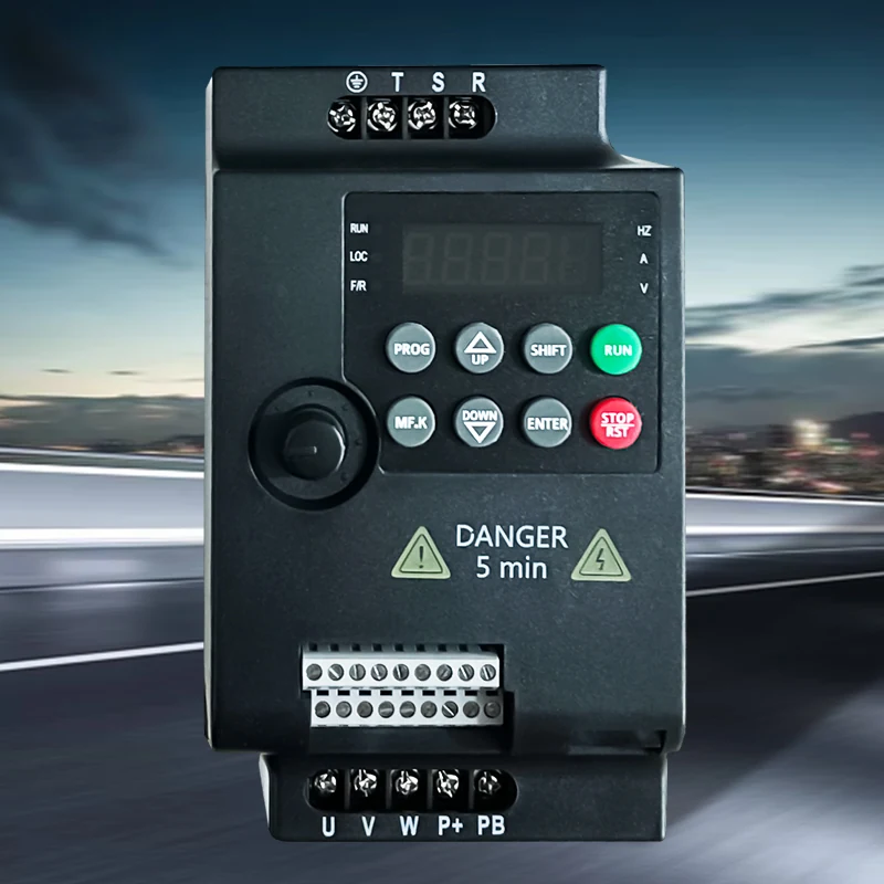
3000 Series Frequency Inverters
Industrial Motor Drives
General motor-control references
High-performance vector drive — general reference manual
Technical reference: match the equipment manual and control-firmware revision before applying terminal or parameter identifiers.
Permanent-magnet motor wiring & parameter setup note
Technical reference: match the equipment manual and control-firmware revision before applying terminal or parameter identifiers.