

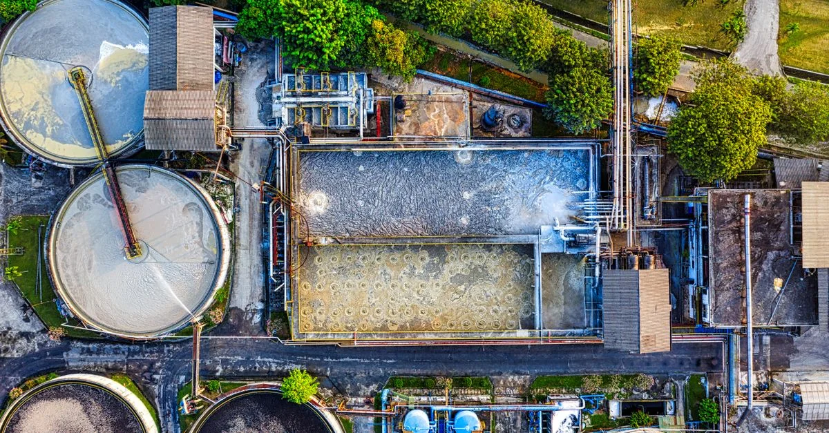
Wastewater pumping & aeration
Wastewater demand changes with inflow and biological treatment conditions. Pumps and blowers require different control variables and protective limits.

Load characteristics & existing operating problems
Wastewater lifting depends on inflow, solids and basin levels, while aeration follows treatment load and oxygen demand. Low pump speed may increase blockage risk; insufficient blower flow can leave its permissible operating region. Assess hydraulic and process constraints first and evaluate lifting, recirculation and aeration separately instead of treating all as the same pump duty.
- Level / flow / oxygen measurement
- plant PLC
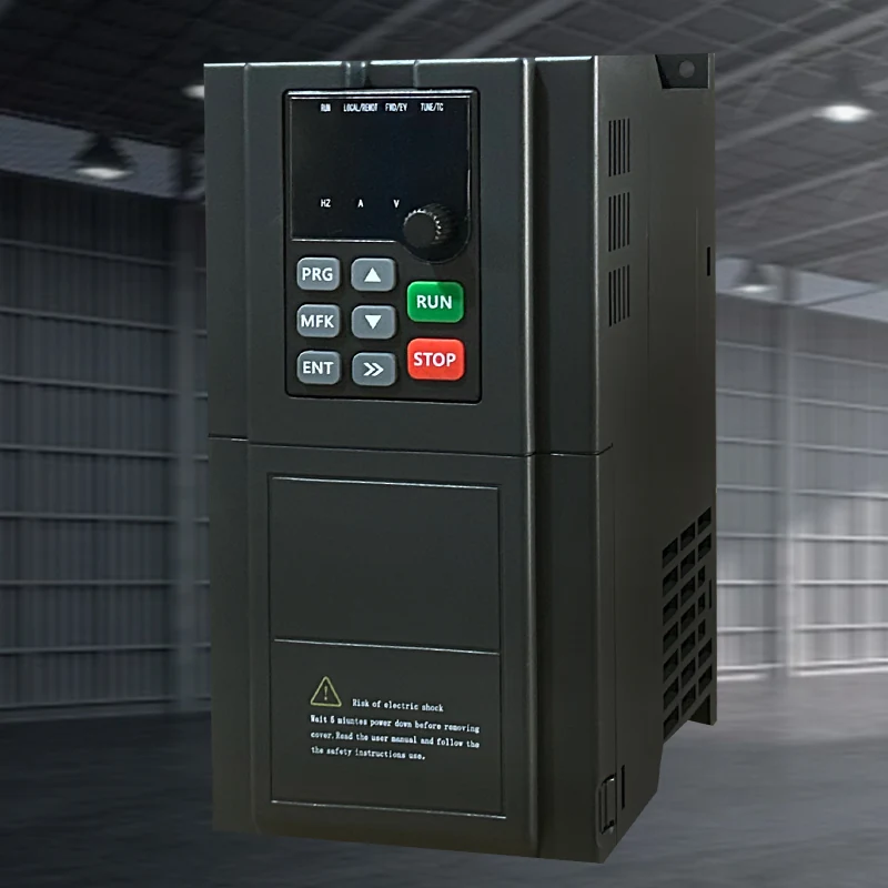 Hailing 790selected drive
- pump or blower
System composition & control sequence
The plant PLC issues bounded speed demands from level, flow or oxygen requirements and manages standby units and alarm escalation. Define independent handling for critical high level, low flow and equipment protection, including operation during sensor cleaning. Drive status feedback uses verified interfaces; a general communication port is not a complete wastewater-control system.
Selection inputs & control requirements
Check pump solids passage, minimum flow, blower surge limits, oxygen-control strategy, motor current and corrosive atmosphere. Validate all sensor interfaces and fallback operating modes.
| Data to collect | Why it matters | Reference |
|---|---|---|
| Basin levels, flow and peak inflow | Establish lifting duty, standby requirements and high-level response. | Hydraulic/process design and site records. |
| Pump passage and minimum flow | Limit solids blockage and damage from low-flow operation. | Pump-maker data and actual medium conditions required. |
| Blower envelope and oxygen demand | Avoid surge, overheating or insufficient treatment air. | Blower curves and treatment-control requirements, not the VFD frequency ceiling. |
| Corrosive environment and signals | Determine cabinet placement, condensation control and signal-failure response. | 790/3000/7000 are candidates; enclosure and terminals require engineering verification. |
Capability and safety boundaries
Use an engineered enclosure; a drive’s generic protective description is not a hazardous-area approval.
Application scenario / design example
APPLICATION SCENARIO / SELECTION EXAMPLEAssume a plant has strongly varying inflow and a separate aeration basin. Establish independent flow/level records for lifting and air-demand records for aeration, then select candidates within each machine’s envelope. The PLC manages level scheduling and standby, while oxygen demand and blower limits jointly constrain aeration speed. Trials record energy alongside basin levels and treatment condition. Any fixed operating mode during sensor maintenance must be approved in advance; a failed signal is not permission to reduce required treatment duty.
Commissioning & acceptance checks
Test level/oxygen signal loss, blocked-flow response, blower minimum speed, alarm escalation and standby sequencing.
- Verify pumps/valves, sensor ranges, earthing and cabinet conditions; check level indication and alarm elevations, and preserve original controls and manual procedures.
- At permitted duties, record flow, level, current and air delivery while process personnel assess treatment response. Tuning must not undercut manufacturer minimum-flow limits.
- Under approved test conditions, verify sensor loss, standby operation and high-level alarms, including maintenance and recovery modes. Do not simulate savings by removing necessary aeration.
Assessing energy and operating value
Compare pumping by useful treated volume and actual head. Aeration comparisons must also match incoming load, oxygen target and treatment performance. Meter units and standby separately and record seasonal/water-quality changes. A lower main-meter reading alone does not prove process efficiency, especially if discharge quality deteriorates.
Product selection & documents
Start with these product families, then match the exact motor, supply, control interface and operating duty.
790 Series Frequency Inverters
Industrial Motor Drives
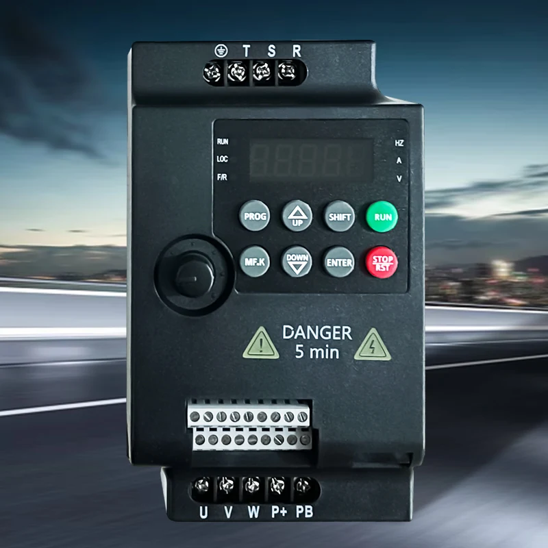
3000 Series Frequency Inverters
Industrial Motor Drives
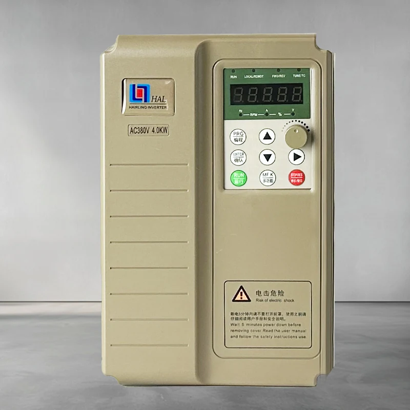
HL7000 Series Frequency Inverters
Industrial Motor Drives
General motor-control references
High-performance vector drive — general reference manual
Technical reference: match the equipment manual and control-firmware revision before applying terminal or parameter identifiers.
Permanent-magnet motor wiring & parameter setup note
Technical reference: match the equipment manual and control-firmware revision before applying terminal or parameter identifiers.