

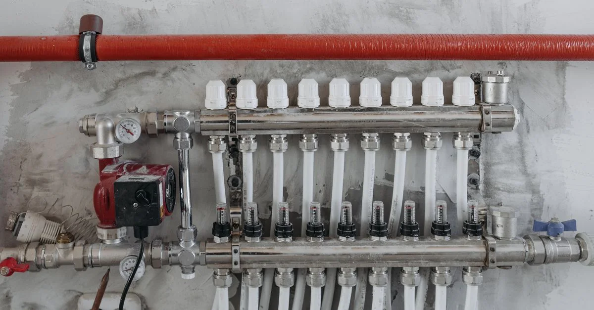
Boiler fans & process circulation
Combustion air and circulation demand vary with process load. Drive control must remain subordinate to the boiler’s certified combustion and safety system.
Load characteristics & existing operating problems
Boiler draught fans, forced-draught fans and circulation pumps follow thermal load but are constrained by minimum flows and purge requirements. Dampers may waste energy, yet unstable combustion, fouled heat-transfer surfaces and water-circuit problems cannot be solved by a drive alone. Boiler specialists must establish the safe envelope before discussing motor-speed changes; electrical control is not a combustion-system retrofit.
- Boiler / process controller
- verified speed command
 Hailing 790drive
- fan or circulation pump
System composition & control sequence
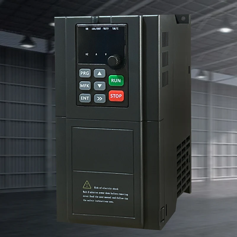
The existing combustion/process controller retains purge, ignition, fuel and trip permissions. The drive follows a verified speed command only. Review minimum air/water flow and fault response with boiler interlocks; loss of reference cannot simply default to minimum speed. Existing low-flow and pressure protection must remain active when variable-speed control is added.
Selection inputs & control requirements
Identify minimum air and water flow, furnace-pressure limits, pre/post-purge sequences, motor ratings and control interfaces. Confirm all permissives with the boiler equipment supplier.
| Data to collect | Why it matters | Reference |
|---|---|---|
| Thermal duty and minimum flow | Establish safe modulation limits and prevent low-flow damage or invalid combustion conditions. | Explicit boiler-manufacturer and process-design requirements. |
| Fan/pump curves and motors | Distinguish airflow pressure, furnace pressure and circulation head. | Equipment curves, nameplates and site measurements. |
| Purge, permissions and fault mode | Keep sequencing consistent with original safety protection. | Original boiler controls; the drive is not a burner-management system. |
| Interface and backup arrangement | Verify commands and fault feedback and prevent unsafe bypass switching. | 790/3000/7000 are candidates; verify actual terminals and switching circuits. |
Capability and safety boundaries
A VFD is not a burner-management system.
Application scenario / design example
APPLICATION SCENARIO / SELECTION EXAMPLEAssume a process-boiler circulation pump runs at fixed speed with throttling at low thermal demand. Obtain the boiler minimum-flow requirement and pump curve, then measure flow, differential pressure and motor duty. If modulation is permitted, the original controller issues a bounded speed demand and retains the low-flow trip. Boiler risk assessment determines drive-fault handling. Trial records separate heat service and electrical consumption across thermal loads without claiming reduced fuel use or guaranteed boiler efficiency.
Commissioning & acceptance checks
Validate purge permissions, minimum flow, control-signal failure and safe stop/restart with the boiler supplier.
- Boiler personnel first confirm instruments, interlocks and permissions, preserve the original control strategy and review drive circuits under agreed maintenance/trial conditions.
- At permitted thermal loads, record flow, pressure, current and temperature and check minimum flow and transients. Combustion adjustments remain with the appropriate specialist.
- Jointly verify signal failure, low flow, fault stop and power recovery using approved procedures, ensuring speed control cannot bypass purge or restart permissions.
Assessing energy and operating value
Relate fan/pump electricity to the same thermal service, flow and environmental conditions, measuring fuel and electricity separately. Isolate effects from cleaning, heat-load changes and water temperatures. Reduced heat delivery or shortened required purges cannot be counted as an efficiency benefit.
Product selection & documents
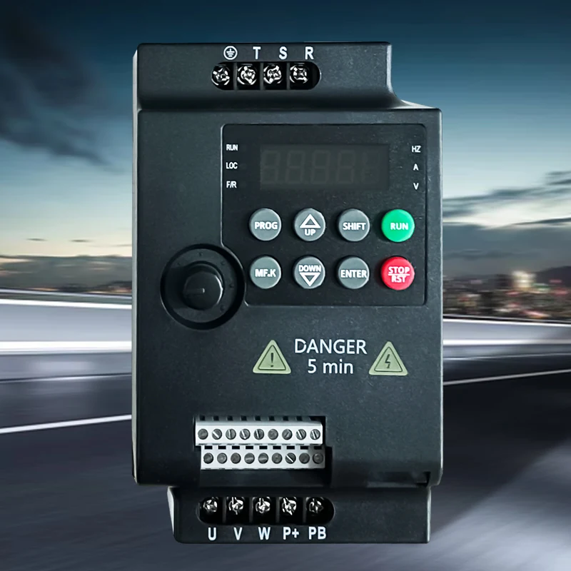
Start with these product families, then match the exact motor, supply, control interface and operating duty.
790 Series Frequency Inverters
Industrial Motor Drives
3000 Series Frequency Inverters
Industrial Motor Drives
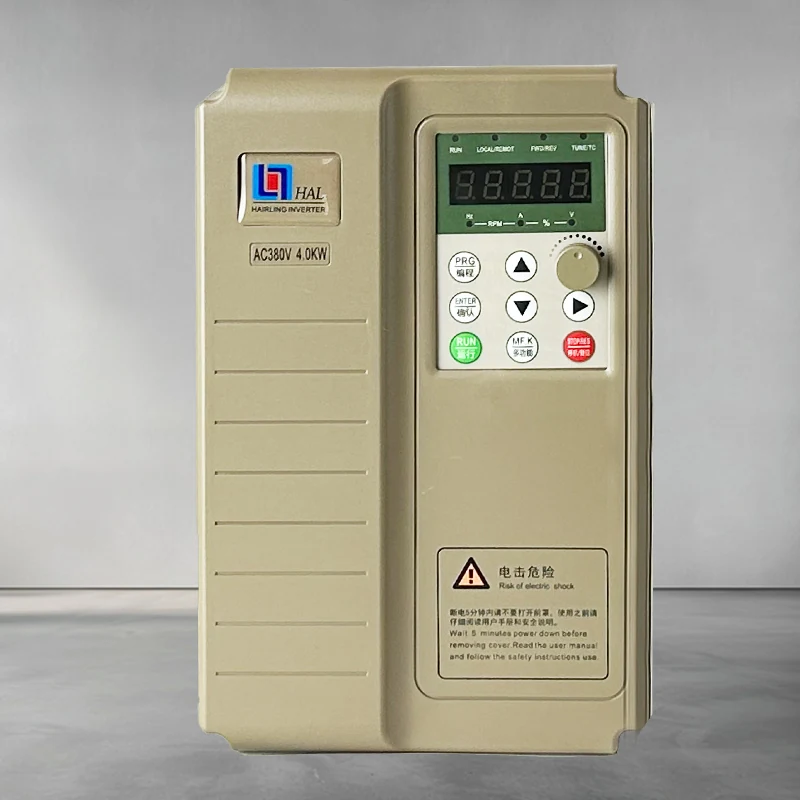
HL7000 Series Frequency Inverters
Industrial Motor Drives
General motor-control references
High-performance vector drive — general reference manual
Technical reference: match the equipment manual and control-firmware revision before applying terminal or parameter identifiers.
Permanent-magnet motor wiring & parameter setup note
Technical reference: match the equipment manual and control-firmware revision before applying terminal or parameter identifiers.