

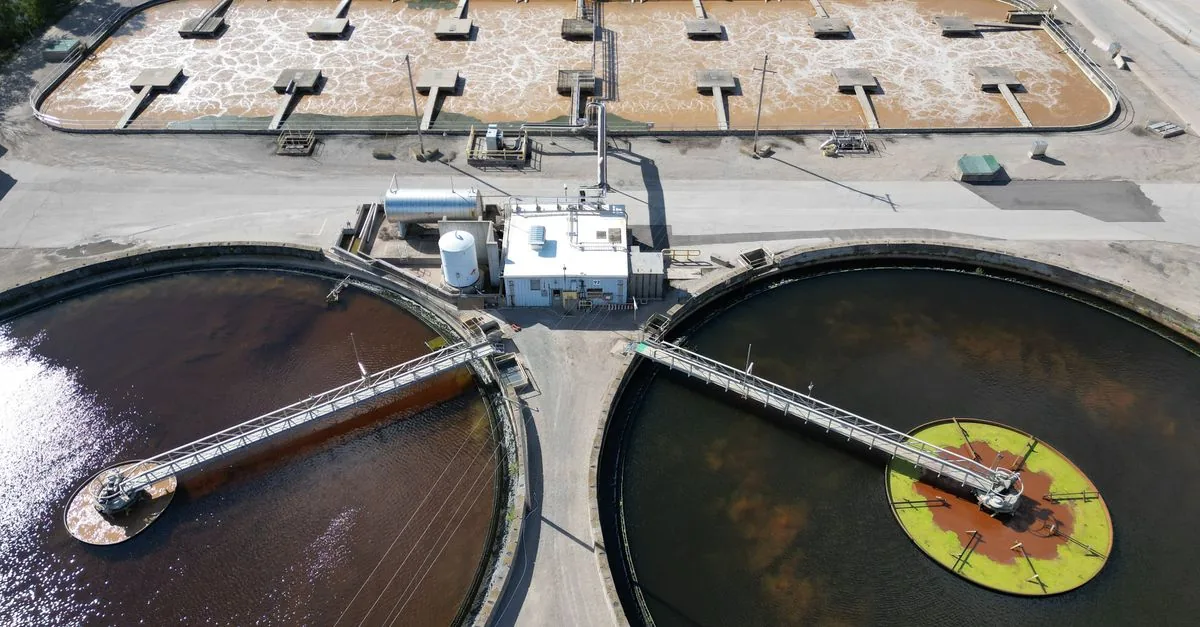
Municipal water supply & treatment
Municipal pumping and treatment loads change with demand, tank level and process stage. Coordinate pressure, flow and standby pumps before choosing a drive.
Load characteristics & existing operating problems
Network demand varies through the day. Pumps can overheat or cavitate at low flow; parallel pumps add changeover shock and reverse-flow risks. Process blowers or dosing pumps have different duties and must not reuse the same parameter set.
- Intake or treated-water pumps
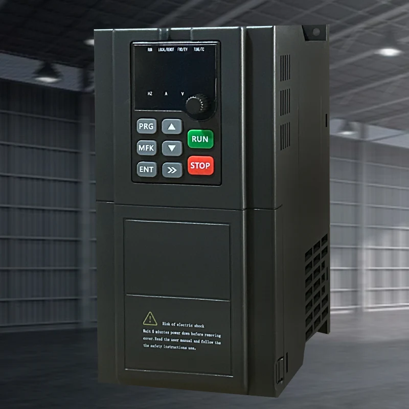 Hailing 790motor and drive
- rising mains or process units
- reservoir or distribution
Pressure or level feedback and pump changeover
System composition & control sequence
Define pressure or level control, minimum frequency, sleep/wake and duty/standby interlocks in advance. The fail-safe action on a lost signal — hold, stop or switch to standby — belongs in the commissioning plan.
Selection inputs & control requirements
Start from pump duty (flow, head, specific gravity), motor nameplate current and the supply voltage. Candidate AC series follow the same water-drive families already used for constant-pressure and wastewater applications: 790, 3000 and HL7000. Confirm the exact configuration.
| Data to collect | Why it matters | Reference |
|---|---|---|
| Pump duty and motor current | Check the operating point and nameplate current against flow, head and the pumped medium. | Pump curve and motor nameplate; not a series rating table. |
| Supply and harmonics | Confirm voltage, short-circuit level and whether the project requires a line reactor or filter. | Project electrical specification; the general manual is reference only. |
| Standby and protection | Define changeover, minimum-flow and dry-run protection. | Site control description. |
Capability and safety boundaries
Company communications mention municipal engineering as an application direction. Harmonic, EMC and redundancy requirements must be confirmed against the project specification.
Application scenario / design example
APPLICATION SCENARIO / SELECTION EXAMPLENight flow is about one third of the peak. The engineer sizes candidate series on peak head and current, then checks minimum frequency and sleep logic so the pump does not run for long with no flow.
Commissioning & acceptance checks
Verify rotation, pressure or level loops, pump changeover, dry-run or minimum-flow trips, and record current at the expected operating speeds.
- Jog each pump to confirm rotation and valve status, then enable the pressure or level loop.
- Verify changeover, lost-signal behavior and minimum-flow protection.
- Record pressure, flow and current at peak and off-peak conditions.
Assessing energy and operating value
Use a delivery flow meter and an energy meter to report specific energy, and record the pressure set-point.
Product selection & documents
Start with these product families, then match the exact motor, supply, control interface and operating duty.
790 Series Frequency Inverters
Industrial Motor Drives
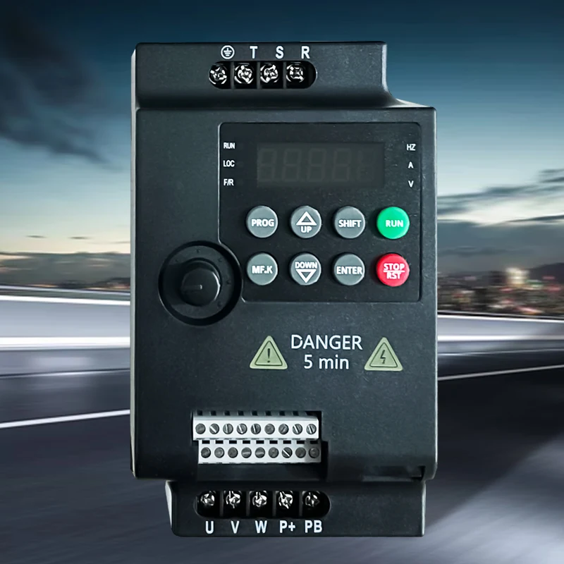
3000 Series Frequency Inverters
Industrial Motor Drives
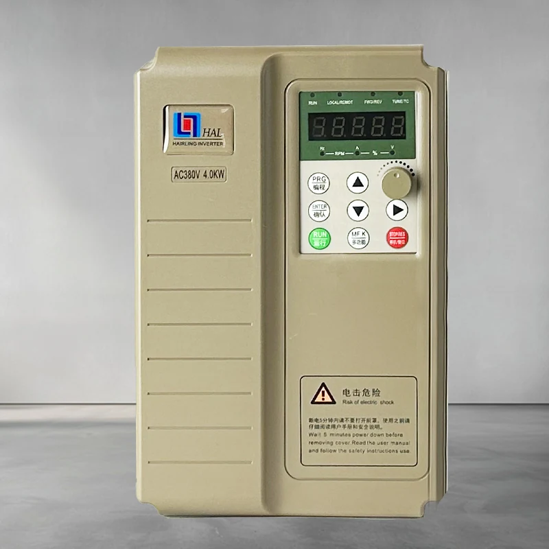
HL7000 Series Frequency Inverters
Industrial Motor Drives
General motor-control references
High-performance vector drive — general reference manual
Technical reference: match the equipment manual and control-firmware revision before applying terminal or parameter identifiers.
Permanent-magnet motor wiring & parameter setup note
Technical reference: match the equipment manual and control-firmware revision before applying terminal or parameter identifiers.