

VFD interference and harmonics: how to cut the path and control the source
Why rectifier and inverter stages create harmonics, how grounding and cable routing stop interference spreading, and when to add line reactors, filters or output reactors.
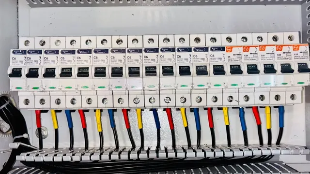
Interference from frequency inverters shows up as harmonics, noise and vibration, load-matching problems and heating. It cannot be avoided entirely: the input rectifier and the output inverter are built from switching (non-linear) devices, and switching distorts the voltage and current waveforms on both the supply side and the motor side.
A single small drive rarely causes trouble. Where drives are large or numerous, the harmonic currents need to be managed, or nearby equipment and sensors may malfunction. Typical sensitivity levels: motors are unaffected below about 10–20% distortion; instruments see errors around 1% at 10% voltage or current distortion; electronic switches may misoperate above 10%; computers may fail above 5%.
1. Cut the propagation path
- Separate earths. Interference often travels through a shared earth conductor. Connect the power equipment earth to the earth line and the control equipment earth to its cabinet metalwork.
- Separate cables. Run high-voltage, power and control cables apart from instrument and computer cables, in different trays where possible. Cross drive control wiring at right angles to main-circuit wiring.
2. Control the harmonics
- Input line reactor. Limits supply-side overvoltage and reduces current distortion at low cost. Its effect is limited, and too much reactance causes an unacceptable voltage drop.
- Passive LC filter on the supply side, usually tuned to the 5th and 7th harmonics. Its performance depends on the supply and the load.
- Active filter. Measures the harmonic current and injects an equal and opposite current to cancel it.
- RFI filter. Where nearby equipment is sensitive to electromagnetic interference, reduce conducted emissions on the supply and use screened motor cable.
- Output reactor. When the motor cable is longer than about 50 m (screened) or 80 m (unscreened), fit a reactor between drive and motor to limit voltage spikes, leakage current and noise.
- Supply impedance. A supply transformer with higher short-circuit impedance reduces harmonic content.
- Multi-pulse supply. Feeding drives from transformer windings 30° apart (for example Y-Δ and Δ-Δ) gives a 12-pulse effect and reduces low-order harmonics.
For the reactor and filter types used with Hailing drives, see the selection guide.
Motor parameter auto-tuning: which method to choose and the step-by-step procedure
Dynamic, static or manual entry? How to choose the right motor auto-tuning method on a Hailing vector drive, the parameters to enter first, and what the drive calculates.
Read more
First start-up: the basic VFD parameters to set before you press RUN
Load type, control mode, command source, frequency source, frequency limits, carrier frequency and ramp times: the P0 group parameters that decide how a Hailing vector drive behaves.
Read more
Permanent-magnet synchronous motor (PMSM) setup: wiring and open-loop parameters
How to wire and commission a permanent-magnet synchronous motor on a Hailing drive in open-loop vector mode, including dynamic auto-tuning and the back-EMF check.
Read more