

Fans, ventilation & HVAC
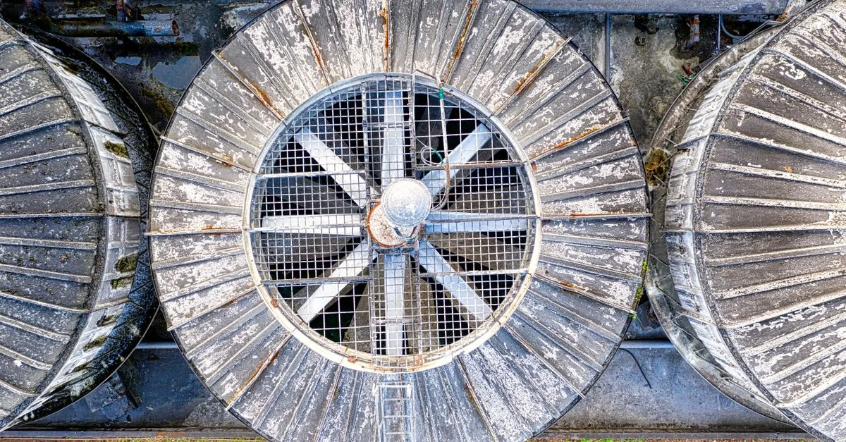
Airflow requirements vary with occupancy, temperature and process duty. Fan speed can be adjusted instead of dissipating excess pressure at a damper.
Load characteristics & existing operating problems
Centrifugal fan airflow and pressure change substantially with speed, but dirty filters, duct modifications and damper positions alter the system curve. Belt drives can limit permissible speed, and sustained low speed affects self-cooled motors. Separate real airflow shortages, measurement errors and excessive ventilation before assessing a retrofit; motor nameplate power alone does not establish its potential.
- Airflow / pressure / temperature sensor
- building controller
 Hailing 3000drive
- fan motor
System composition & control sequence
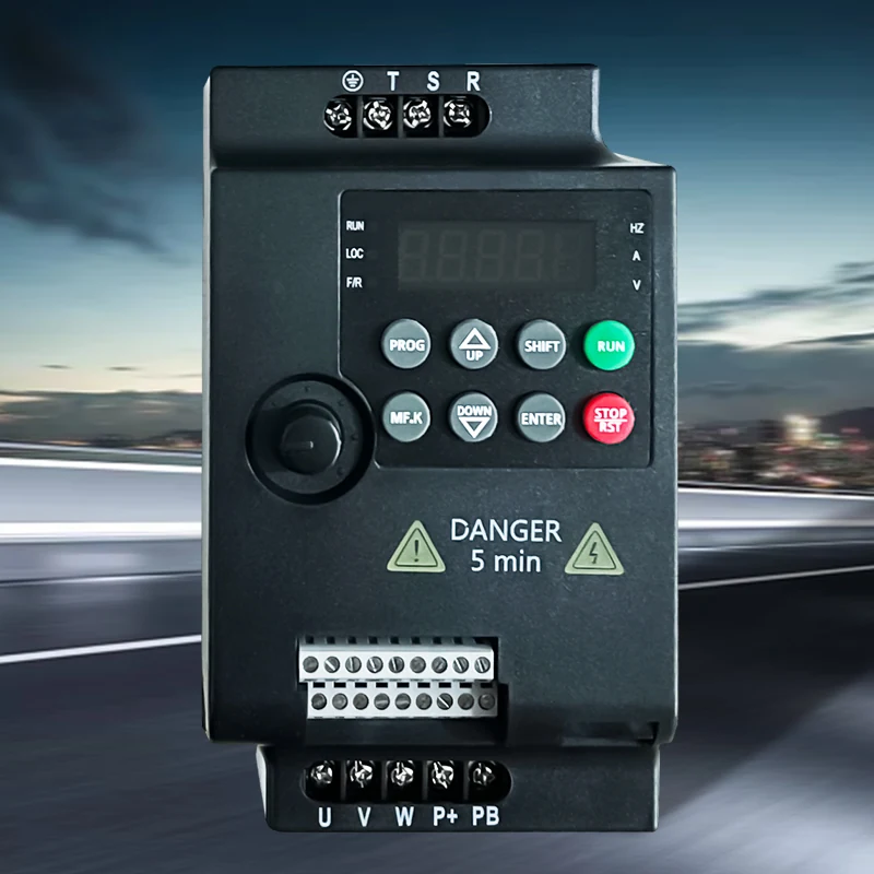
A duct-pressure, temperature or process demand produces a speed reference, while the building or process controller manages permissions and operating modes. Minimum ventilation, mechanical speed limits and identified resonance bands constrain the drive range. Separate fire and hazardous-gas extraction duties from routine comfort control; ordinary PID logic must not be assigned an unverified safety function.
Selection inputs & control requirements
Check fan curves, minimum ventilation, motor cooling, belt ratios, resonance bands, controller interface and fire-system requirements. Confirm flying-start capability separately if windmilling restart is required.
| Data to collect | Why it matters | Reference |
|---|---|---|
| Target airflow and minimum ventilation | Set the lower speed boundary so reduced power does not defeat ventilation. | HVAC design and occupational-hygiene requirements, confirmed for the project. |
| Fan curve and transmission ratio | Check motor/impeller speeds, belt loading and the efficient operating region. | Fan and motor manufacturer data required. |
| Pressure or temperature measurement | Choose a representative sensing point, avoiding turbulence or short-circuit airflow. | Control-system design; verify the ordered model’s signal interface. |
| Environment and windmilling restart | Check dust, cabinet temperature and reverse airflow; verify any required flying-start function. | 3000/790/7000 material supports fan use, not the availability of every option. |
Capability and safety boundaries
An ordinary drive is not a smoke-control safety controller.
Application scenario / design example
APPLICATION SCENARIO / SELECTION EXAMPLEAssume a workshop needs more extraction during production but still requires minimum air exchange during breaks. Measure both duties and confirm contaminant-control requirements before the process controller selects their setpoints. Variable-speed operation follows demand, while filter differential pressure informs maintenance. If vibration increases in a speed band, resolve the mechanical resonance before finalizing the operating range. Trial conclusions prioritize adequate ventilation and acceptable vibration without assuming a saving percentage.
Commissioning & acceptance checks
Check airflow at the minimum setting, vibration through the speed range, acceleration and sensor-loss response.
- Record baseline airflow, pressure, damper position and filter condition. Inspect belts, bearings and impeller rather than trying to correct mechanical faults through drive tuning.
- Increase and decrease speed in stages while recording airflow, vibration, current and temperature. Investigate resonance or belt abnormalities and use approved mechanical changes or speed limits.
- Verify sensor-failure response, building-mode changes and minimum ventilation; inspect windmilling after stop. Associated fire-system actions require acceptance by the appropriate specialist.
Assessing energy and operating value
Compare power at equivalent production schedules, outdoor conditions, filter state and useful airflow. Integrate measured input power over the period and evaluate it alongside minimum-airflow constraints. Do not apply the speed-cubed estimate directly to an entire system with static-pressure requirements, changing efficiency or interacting equipment.
Product selection & documents
Start with these product families, then match the exact motor, supply, control interface and operating duty.
3000 Series Frequency Inverters
Industrial Motor Drives
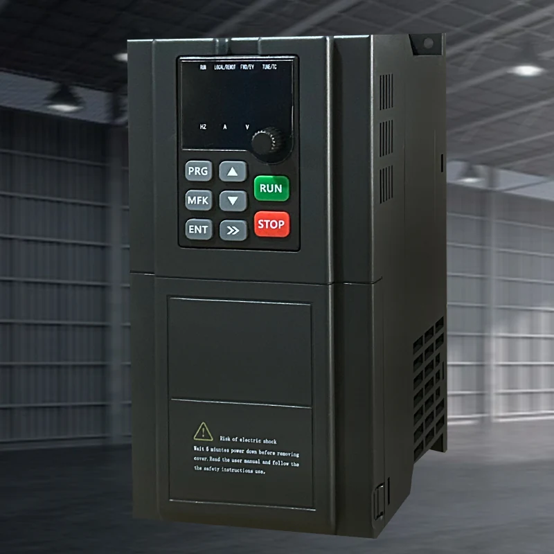
790 Series Frequency Inverters
Industrial Motor Drives
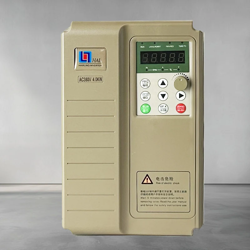
HL7000 Series Frequency Inverters
Industrial Motor Drives
General motor-control references
High-performance vector drive — general reference manual
Technical reference: match the equipment manual and control-firmware revision before applying terminal or parameter identifiers.
Permanent-magnet motor wiring & parameter setup note
Technical reference: match the equipment manual and control-firmware revision before applying terminal or parameter identifiers.