

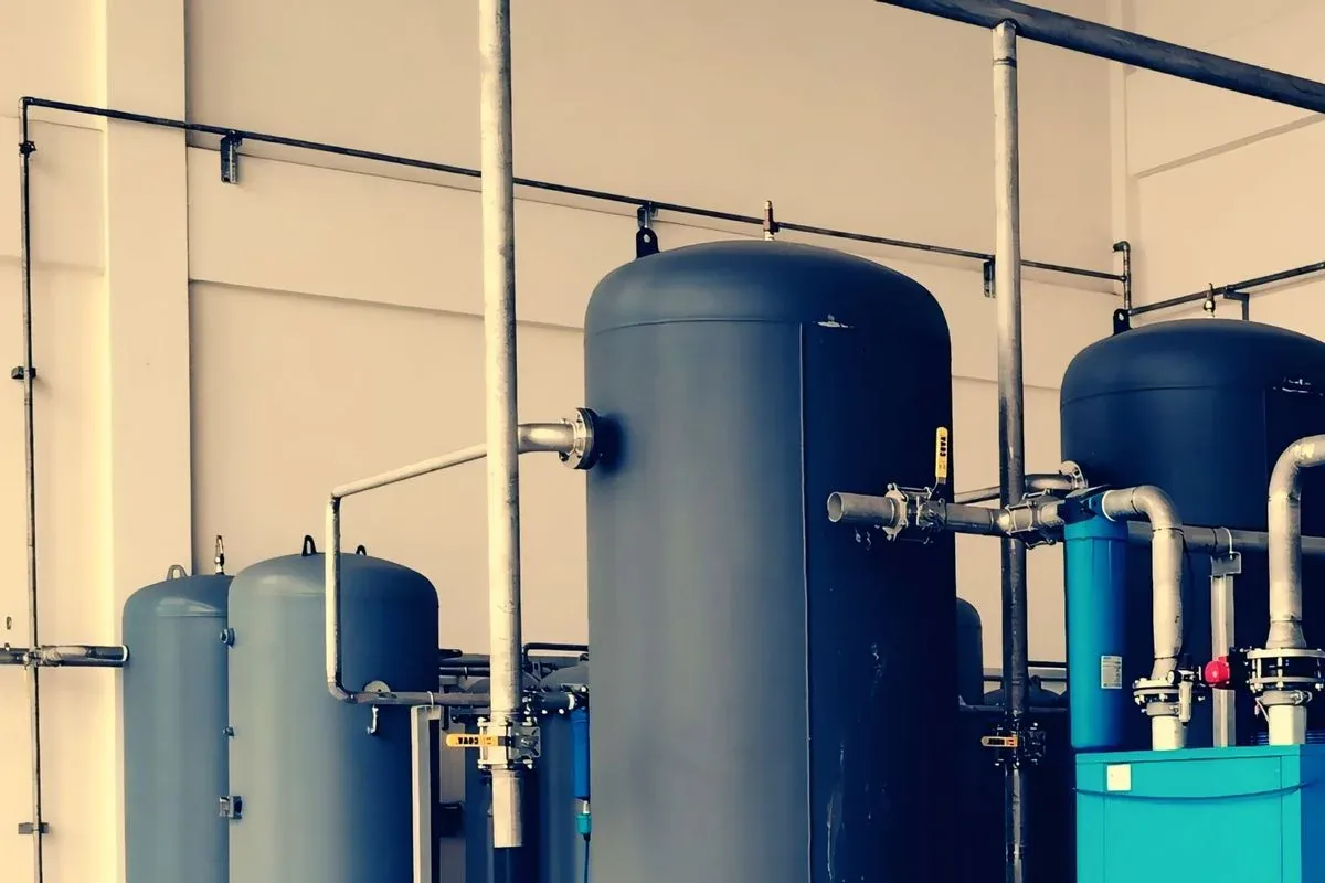
Air compressors & pressure control
Compressed-air demand and unloading time should be measured before considering speed control. Compressor lubrication, cooling and pressure limits take priority over energy targets.

Load characteristics & existing operating problems
Unloaded consumption, network leakage, receiver capacity and pressure setpoint all influence compressor efficiency. Screw compressors can have low-speed lubrication and cooling constraints; reciprocating and permanent-magnet machines have different requirements. Record load/unload cycles and minimum terminal pressure to distinguish sustained supply mismatch from transient demand rather than assuming every problem calls for a replacement drive.
- Pressure sensor
- compressor controller with protection
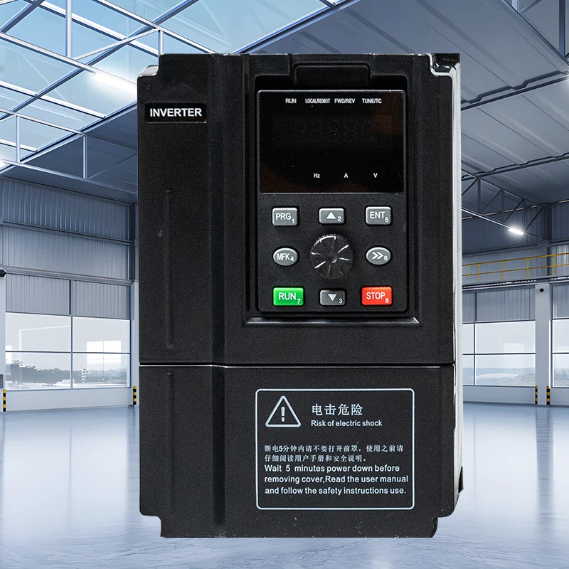 Hailing 750verified drive/motor combination
- compressor
System composition & control sequence
The original compressor controller retains responsibility for temperature, oil pressure, unloading and stopping sequences. A verified control arrangement generates speed demand. Whether target pressure leads to reduced speed, unloading or stopping depends on the compressor’s permitted operation; recovery also considers receiver pressure and restart intervals. HL750/HL7000 are electrical-fit candidates, not evidence of a complete compressor-station protocol merely because RS485/Modbus is listed.
Selection inputs & control requirements
Obtain the compressor manufacturer’s permitted speed range, starting torque, motor type, unloading sequence, lubrication requirements and controller interface. HL750/HL7000 public supplier listings substantiate specific electrical configurations, not a compressor-specific program.
| Data to collect | Why it matters | Reference |
|---|---|---|
| Compressor type and permitted speed | Lubrication, cooling and bearing requirements establish minimum and maximum speed. | Compressor manufacturer confirmation required. |
| Motor type and nameplate current | Distinguish induction and permanent-magnet motors and verify continuous duty and starting requirements. | HL750/HL7000 public configurations cover only their listed voltage/power combinations. |
| Pressure log and receiver | Identify leaks, unloading duration and short cycling to establish actual demand. | Site measurement and pressure-vessel records, not drive functionality. |
| Protection chain and interface | Ensure speed-control changes do not bypass oil-pressure, temperature or overpressure protection. | Original machine circuit, controller and exact drive manual must be reviewed together. |
Capability and safety boundaries
Permanent-magnet motor compatibility and oil-pressure control require engineering confirmation. Do not replace an OEM safety controller or assume all compressors support retrofits.
Application scenario / design example
APPLICATION SCENARIO / SELECTION EXAMPLEAssume a plant’s lunchtime demand falls and its screw compressor spends long periods unloaded. First inspect leaks and log pressure and power for a full shift, then obtain the permitted speed range and motor data from the compressor manufacturer. If retrofit compatibility is confirmed, retain temperature, oil-pressure and unloading protection in the original controller; the drive executes only bounded speed demand. During trials, observe both stable delivery and oil-system condition. If demand lies below the viable modulation range, assess storage and machine scheduling rather than further reducing speed.
Commissioning & acceptance checks
Test loaded/unloaded transitions, oil temperature, pressure stability, minimum-speed operation and protective shutdowns.
- Check leakage and existing pressure settings, then log loaded, unloaded and stopped input power. Correct maintainable air-system losses before treating them as drive-retrofit opportunities.
- Test speed stages only within compressor-manufacturer limits, observing oil temperature/pressure, discharge temperature, current and pressure recovery. Do not lower the minimum speed merely to accommodate low demand.
- Use a safe test procedure to verify unloading, pressure-signal failure and protective stop, including authorization and restart timing after power recovery. Relief-valve and vessel inspection remain separate regulated tasks.
Assessing energy and operating value
Compare electricity per unit of useful air at equivalent terminal pressure and air quality, including loaded, unloaded and standby energy. Attribute leakage repairs, pressure changes and production changes separately. Unverified low-speed operation, reduced pressure service or another brand’s project saving must not be counted as this design’s benefit.
Product selection & documents
Start with these product families, then match the exact motor, supply, control interface and operating duty.
HL750 Series Frequency Inverters
Industrial Motor Drives
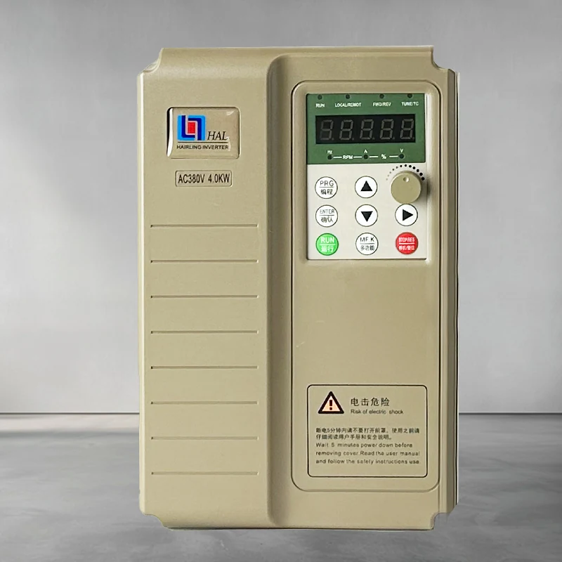
HL7000 Series Frequency Inverters
Industrial Motor Drives
General motor-control references
High-performance vector drive — general reference manual
Technical reference: match the equipment manual and control-firmware revision before applying terminal or parameter identifiers.
Permanent-magnet motor wiring & parameter setup note
Technical reference: match the equipment manual and control-firmware revision before applying terminal or parameter identifiers.