


Constant-pressure water supply
Variable demand makes fixed-speed throttling difficult to manage. Match motor speed to the pressure requirement while respecting the pump operating envelope.

Load characteristics & existing operating problems
Water systems experience hourly peaks as well as rapid valve movements. Required head includes building elevation and pipe losses; prolonged low-speed operation may leave the permitted pump envelope. Poor sensor location, excessive pressure setpoint and pressure disturbances during pump staging are common problems and should not be mistaken for inadequate drive capacity.
- Pressure transmitter
- verified controller or PLC
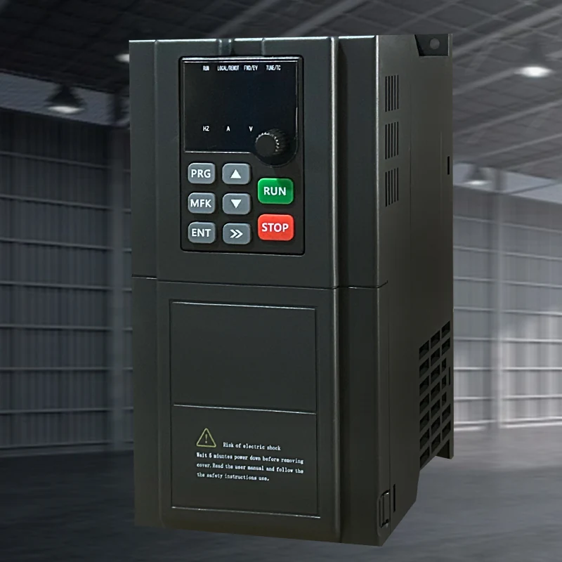 Hailing 790selected motor drive
- pump
- distribution network
System composition & control sequence
A verified controller compares pressure feedback with the setpoint and produces a speed demand. Multi-pump installations additionally coordinate staging, rotation and standby response. The drive executes a bounded speed command, with defined responses for water shortage, excess pressure and maintenance isolation. Verify whether the exact model provides internal PID or sleep/wake functions rather than enabling them by assumption.
Selection inputs & control requirements
Collect the duty flow/head, pump curve, pressure range, minimum flow, sensor signal and number of pumps. Confirm PID, sleep/wake and multi-pump logic for the ordered model; do not infer these from a family name.
| Data to collect | Why it matters | Reference |
|---|---|---|
| Demand profile and service pressure | Determine individual pump duty, staging conditions and an acceptable pressure band. | Project flow records and network design. |
| Pump curve and minimum continuous flow | Bound low-speed operation to avoid overheating or instability at persistently low flow. | Required from the pump manufacturer; cannot be inferred from motor power. |
| Sensor range and signal | An oversized range reduces useful resolution; signal failure requires a defined response. | Exact controller/drive terminal documentation required. |
| Motor current and multi-pump circuit | Check each motor current, switching arrangement and starts per hour rather than merely summing power. | 3000/790 material identifies water-supply use; multi-pump logic and interfaces need separate verification. |
Capability and safety boundaries
Multi-pump rotation needs a verified controller and interlocked contactors. Automatic mains bypass is not a default feature and must never be wired across a running drive output.
Application scenario / design example
APPLICATION SCENARIO / SELECTION EXAMPLEAssume one pump can serve a building at low demand while peak demand needs a second pump. Measure the demand profile and establish the permissible duty of each pump before a supervisory controller defines staging and rotation. The variable-speed pump supplies continuous pressure adjustment, while switching uses an engineered interlock and timing arrangement. Acceptance considers peak pressure and minimum flow at low demand. If demand is below a practical operating point, review pump grouping rather than continually reducing motor speed.
Commissioning & acceptance checks
Log pressure at low, normal and peak demand; test sensor failure, minimum flow and safe recovery after supply loss.
- Compare pressure indication with a calibrated gauge, verify sensor location, rotation and valve state, and establish a stable duty point using controlled single-pump operation.
- Apply low, medium and high demand stages and record steady pressure, recovery time, current and flow. Distinguish controller behavior from pump/network limitations before tuning.
- Use an approved procedure to test low water, sensor disconnection and standby transfer. Verify that recovery is authorized and mains cannot be connected to an energized drive output.
Assessing energy and operating value
Compare electricity per unit of delivered water at an equivalent pressure service level, recording leaks, setpoints and pump staging. Reduced pressure may lower leakage but is not a valid saving if terminal service pressure is no longer met. Include all pumps and control-cabinet consumption in a multi-pump comparison.
Product selection & documents
Start with these product families, then match the exact motor, supply, control interface and operating duty.
790 Series Frequency Inverters
Industrial Motor Drives
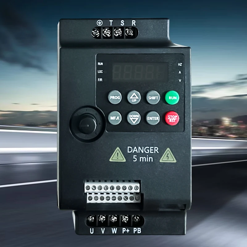
3000 Series Frequency Inverters
Industrial Motor Drives
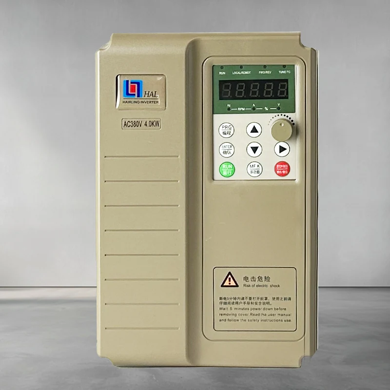
HL7000 Series Frequency Inverters
Industrial Motor Drives
General motor-control references
High-performance vector drive — general reference manual
Technical reference: match the equipment manual and control-firmware revision before applying terminal or parameter identifiers.
Permanent-magnet motor wiring & parameter setup note
Technical reference: match the equipment manual and control-firmware revision before applying terminal or parameter identifiers.